A 3d printing slicer cuts a model into flat layers and writes the G-code, a command format first standardized in 1963, that tells the printer where to move, how hot to run and when to extrude.
This guide belongs to the wider 3d printing topic and explains what the software does, which settings matter and how to pick one.
What a slicer actually does
The G-code that slicers output traces back to 1963, when the Electronic Industries Association published RS-274, the first standardized version used in the United States. Slicers reuse that machine-tool language for printers. According to Wikipedia, a slicer converts a model in STL format into printer commands in G-code format.
The process starts by segmenting the object as a stack of flat layers. Each layer is then described through linear movements of the extruder, the fixation laser or an equivalent component. Temperature commands for the extruder and the bed are compiled into the same file, so the printer needs no knowledge of the original model.
That is why a model file alone cannot print. The same STL produces different G-code on different machines, and the slicer holds the profile that describes each one. This matters most for fdm 3d printing, where filament is melted and deposited line by line.
Why the slicer matters more than the printer
Since 1963, when G-code first became a published standard, the instructions have mattered as much as the machine that follows them. A printer is a motion platform with a heater. Everything that makes a print look good or fail, from wall thickness to travel moves between islands of material, is decided in the slicer before the first line of filament is laid down.
Two people with the same printer and the same model can get very different results simply because their slicers made different choices. One may print outer walls slowly for a clean surface and fill the interior sparsely. Another may favor speed and accept visible ridges. Neither is wrong, but the trade-off is set in software, not hardware.
This is also why upgrading a slicer profile is often the cheapest improvement available. Retuning temperature, cooling and retraction in a profile costs nothing, while a new hotend or frame costs money. Hobbyists often discover that a failing print was a settings problem all along.
- RS-274, the first standardized US G-code, was published in 1963 by the EIA: 1963
- Final RS-274 revision RS-274-D approved in 1979: 1979
- ISO 6983 finalized in 1982: 1982
- A slicer converts STL models into G-code: STL to G-code
- Slicers segment objects into flat layers: stack of flat layers
Settings that change your results
Two main types of support structure exist in slicers: the standard zig-zag lattice and the tree structure. Both exist because each new layer sits directly on the one below, so floating layers such as the roof of a house need something beneath them.
Tree supports are considered easier to remove and consume less filament, as a main branch grows from the bed and reaches out to hold up overhangs. Lattice supports remain predictable on flat undersides.
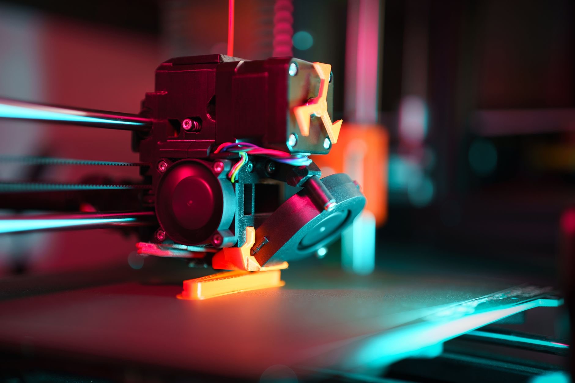
Infill is the second big lever. Printing a solid object takes a significant amount of material and time, so slicers convert solid volumes to hollow ones with an internal pattern, saving filament and cutting print time. The first layer has its own options: a skirt, a brim or a raft, each added to improve adhesion to the bed.
A practical way to learn is to change one setting at a time and print a small test piece. Switch infill from sparse to dense, compare the weight and the time estimate, and note the difference. Do the same with supports: print an overhang with lattice supports, then again with tree supports, and compare how cleanly the structure breaks away and how much filament it used. Slicers also display a layer-by-layer preview, which lets a user spot gaps, stringing paths and unsupported islands before wasting material.
Adhesion options deserve the same experimentation. A skirt is a loop printed near the part that primes the nozzle without touching it. A brim widens the first layer with a flat ring attached to the part. A raft builds a sacrificial base under the whole object. Each trades material and cleanup effort for a better chance that the first layer stays flat on the bed.
Compatibility and file formats
G-code was standardized in 1963, revised as RS-274-D in 1979 and finalized as ISO 6983 in 1982, yet printers still read dialects of it. Firmware flavors differ in how they handle commands such as temperature and acceleration, so the slicer must be set to the correct flavor for the printer.
In practice, check three things before committing: that the slicer ships a profile for the printer, that it reads the model formats the workflow produces, and that it exports G-code the firmware accepts. A mismatched flavor is a common source of a printer that heats up and then does nothing.
Model formats add a second layer of compatibility. STL is the common input described by Wikipedia, and it carries only surface geometry, with no color, material or unit information. Slicers therefore ask the user to confirm scale on import, and a model exported in inches can arrive looking tiny when the slicer assumes millimeters. Checking the dimensions shown in the slicer against the intended size takes seconds and avoids a failed print.
Wireless and card-based workflows matter too. Certain printers accept a G-code file over the network from the slicer, while others read it from a memory card. Confirm which route the printer supports, because a slicer that can send files directly saves repeated trips between computer and machine.
How to choose a 3d printing slicer
The 1982 ISO 6983 finalization did not end dialect differences, so the first filter is printer support, not feature count. Start with the slicer the manufacturer recommends, because its profile is tested against that hardware.
Next, match the tool to your skill level. Beginners benefit from presets and a simple print-ready view, while experienced users want per-region overrides, modifiers and scripted changes. The cura slicer is a widely used example, and Wikipedia uses Cura screenshots to illustrate infill, supports and adhesion structures.
Finally, favor software with open profiles that can be exported and shared. Switching slicers later is easier when settings are documented, and a free tool is enough to learn the fundamentals before any paid option is worth considering.
Community matters as well. A slicer with an active user base has shared profiles, tutorials and answers to odd failures, which shortens the learning curve far more than an extra menu option does. Check how recently the software was updated, whether the project is documented in public, and whether the license lets you keep using it without a subscription. Run a trial print of a familiar model in two candidates and compare the preview, time estimate and result before settling. Because any good slicer exports standard G-code, trying a second tool carries little risk.
Frequently asked questions
Is a slicer the same as CAD software?
Is a slicer the same as CAD software?
No. CAD creates the model, while a slicer turns an STL file into G-code, a format first standardized as RS-274 in 1963.
Can one slicer drive any printer?
Can one slicer drive any printer?
Only with the right profile and firmware flavor. G-code exists in dialects despite the ISO 6983 standard finalized in 1982.
Why do supports sometimes get added automatically?
Why do supports sometimes get added automatically?
Each layer rests on the one below, so floating areas such as a roof need support. Wikipedia describes two main types: lattice and tree.
Does infill affect print time?
Does infill affect print time?
Yes. Wikipedia notes that hollowing solid volumes with infill saves material and reduces print time.