FDM 3D printing builds an object by melting plastic filament and depositing it layer by layer through a heated nozzle, a process Stratasys co-founder Scott Crump patented in 1988.
It is the most widespread branch of 3d printing, and this guide explains the mechanics, the materials and the limits.
How FDM 3D printing works: melt, extrude, stack
Since the patent on FDM technology expired in 2009, anyone has been free to build such machines without paying Stratasys. That expiry has been credited with a two-orders-of-magnitude price drop since the technology’s creation. Stratasys still owns the trademark on the term “FDM”, which is why RepRap and others adopted the alternative name FFF, short for fused filament fabrication.
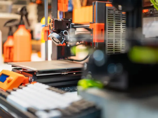
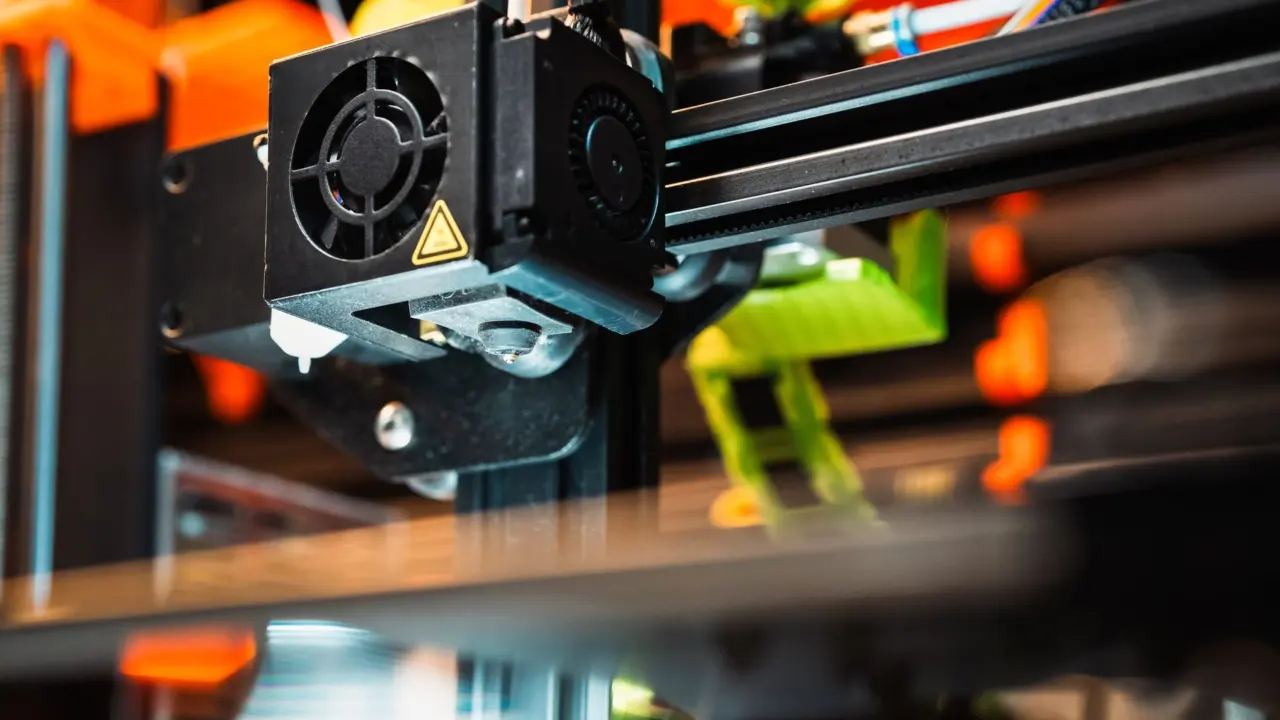
The mechanism is simple. A spool of thermoplastic feeds into an extruder, where a motor pushes the filament into a heated nozzle. The nozzle moves over the build platform in a prescribed geometry and deposits a thin bead of plastic, called a road, which solidifies quickly on contact with the platform or with roads laid earlier. Solid layers come from a rasterizing motion in which the roads sit side by side.
Once a layer is finished, the platform is lowered, or the extruder is raised, along the z axis so the next layer can begin. Repeating this step for every slice turns a stack of flat layers into a solid part.
Two motion systems are common. In a Cartesian design, the toolhead moves in two dimensions to deposit one horizontal plane, while the bed or the head steps vertically by a small amount to begin the next layer. Other designs, such as delta printers, reach the same result with a different arrangement of arms and rails. In every case the controller reads a file of coordinates and extrusion amounts, often called G-code, and executes it line by line.
The printed road has a width set mainly by the nozzle diameter and a height set by the layer height chosen in the slicer. Thinner layers hide the stair-step texture on curved surfaces but lengthen the print time, so the setting is always a trade between appearance and speed. For functional parts, a thicker layer is usually the sensible choice because it prints faster and bonds well.
Print speed, nozzle temperature and part cooling fans work together. A fan solidifies each road quickly, which sharpens fine details and bridges, but too much cooling can weaken the bond to the layer below. Stratasys industrial machines, RepRap-derived hobby printers and enclosed desktop models all handle this trade-off differently, which is why the same file can print with slightly different results on each.
Filament: the raw material
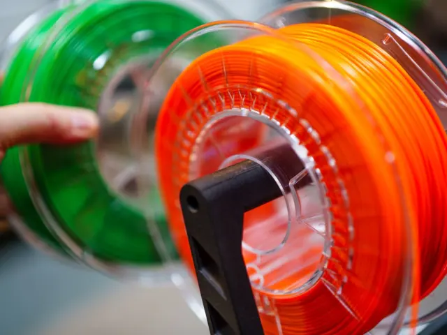
Filament is a continuous slender plastic thread wound on a reel. It comes most commonly in diameters of 1.75 mm and 2.85 mm, and the larger size is often confused with the less common 3 mm. The most common materials are PLA (polylactic acid), PETG and thermoplastic polyurethane (TPU).
Each material trades something against something else. PLA is easy to print and suits prototypes and display models. PETG is tougher and handles moisture better. TPU is flexible and suits gaskets, grips and bumpers. Filament absorbs water from the air, which is why commercial producers dry the plastic nurdles at 80 °C before extruding them, and why spools are shrink-wrapped for sale.
The diameter of the filament is set by the pulling force and speed applied as it leaves the production extruder, not by the nozzle on your printer. A printer built for 1.75 mm filament cannot use 2.85 mm filament without a different hot end.
Why layer adhesion decides strength
Each layer bonds to the one below while still warm, so the adhesion strength of the layers depends on the printing temperature and other print parameters. A part is therefore usually weaker along the layer lines than across them. Orienting a part so that the main load runs along the roads rather than between layers is a common way to gain strength without changing material.
Hotter extrusion and slower cooling generally improve bonding, though heat that is too high causes stringing and sagging. Tuning this balance is most of what experienced users do when a print fails.
Overhangs and supports
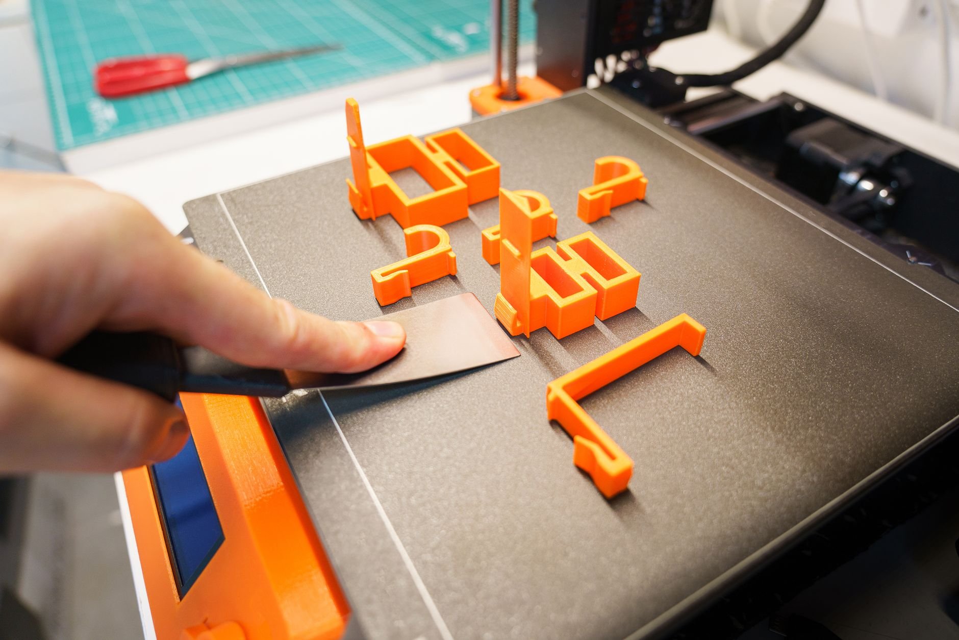
FFF is flexible and can bridge small overhangs by relying on the layers beneath, but it has restrictions on the slope of an overhang and cannot produce unsupported stalactites. Steeper features need support structures, usually printed in the same plastic and snapped off afterwards, which leaves rough patches on the surface.
Designers work around this by splitting models into parts, adding chamfers instead of flat undersides, and choosing orientations that minimise supports. Software called a 3d printing slicer converts the model into the layer paths and decides where supports go.
Common failures and how to read them
Because the process is mechanical and thermal, most failures trace back to a few causes. The Stratasys patent expired in 2009, and the community that grew afterwards, led by RepRap, documented these faults in detail. The main ones are listed below.
- Warping: the corners of a part lift from the bed as the plastic cools and shrinks. A heated bed, a brim, or an enclosure reduces it.
- Stringing: thin threads of plastic cross gaps between features. Lower nozzle temperature and tuned retraction settings usually cure it.
- Under-extrusion: gaps appear in walls because the nozzle is partly clogged or the filament has absorbed moisture. Drying the spool, as producers do at 80 °C, is the first step to try.
- Layer splitting: layers separate because adhesion depends on printing temperature and cooling is too aggressive.
Reading a failed print like a diagnostic report is a core skill. A rough surface points to moisture, a lifted corner points to bed adhesion, and a clean but weak part points to temperature or orientation.
What FDM suits best
Since the 2009 patent expiry, FDM has spread from industrial prototyping into schools, workshops and homes. It suits jigs, brackets, enclosures, replacement parts and design prototypes, where moderate accuracy and good mechanical strength matter more than a glossy finish. Material choice widens the range: PLA for easy models, PETG for tougher parts and TPU for flexible ones.
It is less suited to tiny detailed figurines, transparent parts or very smooth surfaces. Those jobs usually go to other processes, and layer lines on an FDM part can be sanded, filled or chemically smoothed when a finer look is needed.
How FDM compares with resin
Resin systems cure liquid photopolymer with light instead of melting a thread of plastic, which gives a finer surface at the cost of messier handling and post-processing. A fuller comparison is in the guide to resin printing. FDM keeps the advantage in material range, part size and running cost, and the 2009 patent expiry helped make hobby machines affordable.
Frequently asked questions
What does FDM stand for?
What does FDM stand for?
FDM stands for fused deposition modeling. Stratasys owns the trademark, so RepRap and others use the name fused filament fabrication (FFF) for the same process.
When did the FDM patent expire?
When did the FDM patent expire?
The patent on FDM technology expired in 2009, per Wikipedia’s article on fused filament fabrication, which opened the way to low-cost consumer printers.
What filament diameter should a printer use?
What filament diameter should a printer use?
Most printers take 1.75 mm filament, while 2.85 mm is the other common size. Check the hot end specification before buying a spool.
Why do prints split between layers?
Why do prints split between layers?
Layer adhesion depends on printing temperature and other parameters, according to Wikipedia’s fused filament fabrication entry, so a nozzle that is too cool leaves weak bonds.