3d modeling for 3d printing means designing geometry around how a printer builds parts: layer by layer, with a 0.4 mm nozzle on most desktop machines. Overhangs, wall thickness and a flat base decide whether a print succeeds.
Printability is one branch of the wider craft of 3d modeling, and it rewards a different mindset from modeling for renders or games.
Start from the nozzle: wall thickness and feature size
The standard diameter for nozzles on desktop printers is 0.4 mm, according to the Prusa Knowledge Base, and that single number sets the floor for every thin wall and small detail in a model. Prusa’s guide states it bluntly: “Walls thinner than one nozzle perimeter are not printable.”
The extrusion width is slightly larger than the nozzle itself. In PrusaSlicer, a stock 0.4 mm nozzle prints lines 0.45 mm wide, so a wall modeled at 0.45 mm yields exactly one perimeter. Modeling walls as whole multiples of the extrusion width keeps the slicer from filling gaps awkwardly or dropping the wall altogether.
Practical habits follow from this:
- Check the intended nozzle before choosing minimum thickness for walls, pins and text.
- Make raised lettering and fine ribs several line widths wide, not one.
- Exaggerate small features slightly in the model; a decorative detail that looks fine on screen can vanish in the slicer preview.
Overhangs, bridges and the 45-degree rule
Prusa reports that a printer can cleanly print overhangs between 45 and 60 degrees, depending on nozzle diameter and settings. Protolabs Network (formerly Hubs) calls overhangs “one of the most common FDM print-quality problems” and recommends support for wall angles above 45°.
Overhangs occur when a layer is only partially supported by the layer below it. Beyond the limit, the plastic droops, and the underside turns rough. Smaller nozzles make this worse: Prusa notes that for a 0.25 mm nozzle the usable angle might be less than 45 degrees.
Design the overhang away
The cleanest fix is geometry. Replace a flat ceiling over a cavity with a chamfer or a teardrop shape, so that no surface leans out further than the printer can manage. Prusa also suggests modeling in break-away supports, or splitting a part into several pieces that each print in a better orientation.
Bridges
Horizontal holes in walls and the roofs of hollow parts become bridges. Protolabs Network warns that sagging or support marks are always present to some extent unless the bridge spans less than 5 mm. Keeping spans short, or stepping a hole into a diamond shape, avoids the problem without any support at all.
Orientation for 3D printing and the first layer
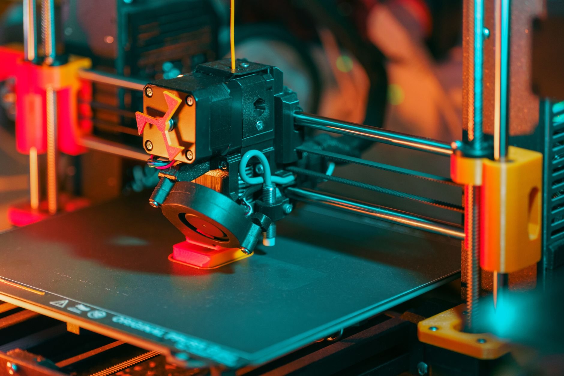
Protolabs Network advises a 45° chamfer or radius on every edge touching the build plate whenever assembly or overall dimensions are critical. The reason is the first layer: it is squashed against the bed, and that squashing bulges the bottom edge outward, an effect often called elephant’s foot.
Orientation matters beyond appearance. Prusa’s guide says that for fused filament fabrication, orientation and geometry greatly affect both the look and the integrity of the print. Layer lines are the weak planes of a part, so a clip or hook printed standing up can snap along them where the same shape printed flat would flex.
When a single orientation cannot satisfy every requirement, split the model. A box and its lid, or a bracket cut into two flat-based halves, often prints faster, cleaner and stronger than one complicated piece with extensive supports.
Designing for the printer you own
Every rule above shifts with the machine. A 0.4 mm nozzle sets different limits from a 0.25 mm one, and Prusa’s guide ties the usable overhang range of 45 to 60 degrees to nozzle diameter and settings. A model drawn for one printer may therefore need small edits for another, even when both are desktop filament machines.
A useful workflow is to keep the design parametric. Store wall thickness, clearance and chamfer size as named parameters near the top of the file, so that a change of nozzle or material means editing a handful of values rather than redrawing features. Parametric CAD such as Fusion, FreeCAD and OpenSCAD supports this directly, and mesh sculpting tools can be paired with it for organic shapes.
Material changes the picture as well. Flexible and engineering filaments shrink and warp differently from standard PLA, so test pieces printed in the final material are worth more than any rule of thumb. Writing the settings that worked into the file’s notes saves the next iteration from starting blind.
Holes, tolerances and fit
Protolabs Network describes a quirk of vertical holes: as the nozzle prints the perimeter, it compresses the new layer down onto the layers beneath, which reduces the finished diameter. Its recommendation is that when a hole diameter is critical, it should be printed undersized and then drilled to the correct size.
For moving or mating parts, model clearance deliberately rather than relying on exact dimensions. Printers do not reproduce a digital value perfectly, so test with a small calibration piece, a short print with a few pin and hole pairs at different gaps, and then apply the gap that works to the full design. Prusa’s guide also recommends planning for several iterations of a design, since the first version rarely fits.
Clean geometry: manifold, watertight and exportable
Prusa’s guide lists a “Make sure it is manifold/solid” step among its core checks. A slicer needs to know which side of every surface is inside the object, so holes in the mesh, flipped normals or zero-thickness faces lead to missing layers or failed slices.
Before export, run the mesh-repair or 3D-print check built into the modeling package, look at the slicer’s layer preview, and scrub through it rather than trusting the 3D view. File type matters too; Protolabs Network publishes a separate guide to STL, 3MF, OBJ and STEP, and 3MF or STEP preserve more information than STL.
Common mesh faults are worth knowing by name. Non-manifold edges join more than two faces. Internal faces hide inside a solid after a sloppy boolean operation. Duplicate vertices leave hairline cracks that are invisible in a shaded view. Each one can confuse the slicer about where material belongs, so cleaning them in the modeling package costs far less time than diagnosing a failed print afterward.
Models do not always begin as clean CAD. Scanned geometry usually needs hole filling and smoothing first, which is covered in the guide on how to 3d scan an object. For a broader definition of the digital object itself, see the entry on what a 3d model is.
Frequently asked questions
What is the minimum wall thickness for a 3D print?
What is the minimum wall thickness for a 3D print?
Prusa’s guide says walls thinner than one nozzle perimeter are not printable. With a 0.4 mm nozzle and a 0.45 mm extrusion width in PrusaSlicer, one perimeter is 0.45 mm.
What overhang angle can be printed without supports?
What overhang angle can be printed without supports?
Prusa states that angles between 45 and 60 degrees print cleanly, depending on nozzle diameter and settings. Protolabs Network recommends support above 45°.
Why do printed holes come out too small?
Why do printed holes come out too small?
Protolabs Network explains that the nozzle presses each new perimeter down as it prints a vertical hole, shrinking the diameter. Its advice is to print critical holes undersized and drill them to size.
Do I need to split a model into parts?
Do I need to split a model into parts?
Prusa’s guide suggests splitting a part into multiple pieces when that gives each one a better orientation on the bed, which reduces supports and improves surface finish.